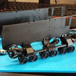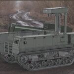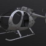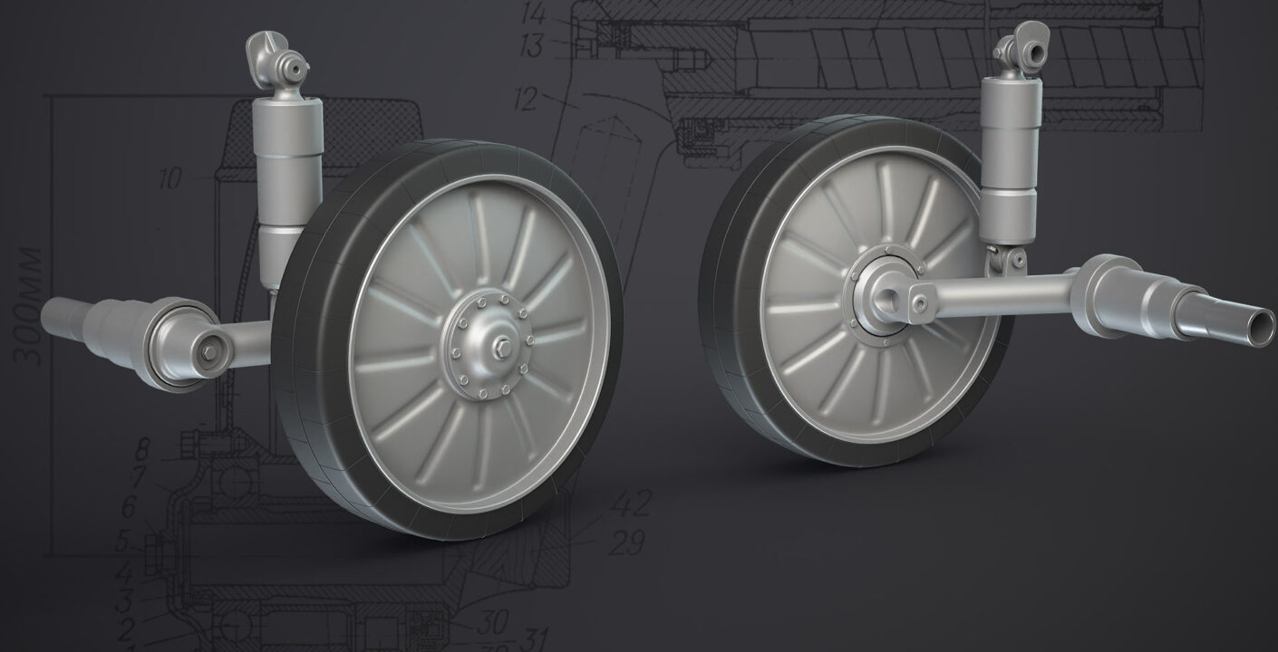
The more references you have, the more possibilities you get. This short post is about a simple lifehack that, personally, wasn’t obvious to me at first. Now I use this method every time I need to create a highly detailed 3D model of armored vehicles.
I think many 3D artists eventually reach a point where they want to create a model so detailed that it feels “just like the real thing.” Usually, after a certain amount of effort and lots of time spent, people abandon the project before finishing it. I already have several such unfinished models. The main reason is the lack of time and motivation needed to complete a large project. Also, at the beginning, an artist may have unrealistic expectations and excessive perfectionism, which can quickly clash with the simple lack of reference materials, technical knowledge, and 3D modeling skills.
You might think that having full blueprints would make modeling a tank easy. But in reality, having all the blueprints for a vehicle is physically impossible. For example, around 10,000 technical drawings were made for the T-34 tank. Every part and assembly was developed by different design bureaus where dozens or even hundreds of professional engineers worked. If you’re just a 3D modeler, you should accept that you’ll never be able to create an absolutely accurate replica of a real machine. So it’s always important to find a compromise that matches real-world constraints and the references you actually have.
I have to rely on whatever blueprints, photos, and technical data I can find online. While modeling the running gear of the BMP-1 (BMP-2), I ran into the problem that I simply couldn’t find the dimensions of the road wheel arm (balancer) and the hydraulic shock absorber within a reasonable time. However, I do have the diameter of the road wheel and this blueprint:
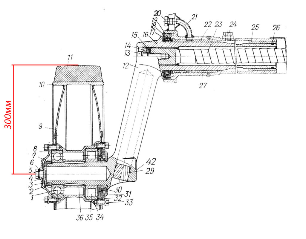
Knowing the wheel diameter, I can use this drawing to model the balancer and its mounting bracket. Next, I need to create the hydraulic shock absorber—but its dimensions are unknown to me. Still, I do have this drawing:
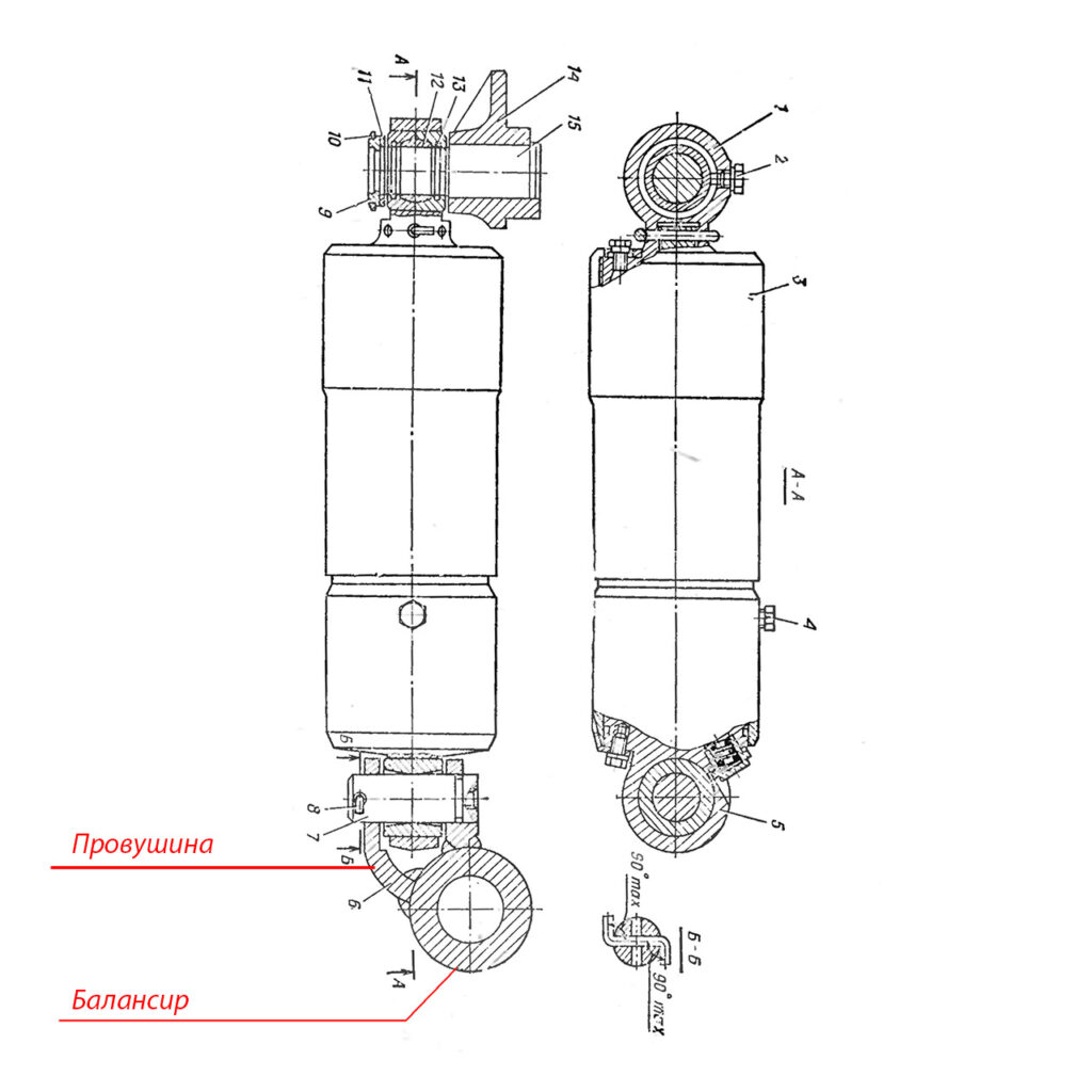
After figuring out what exactly is shown in the blueprint, I can simply align the shock absorber drawing in Blender to the balancer I’ve already modeled.
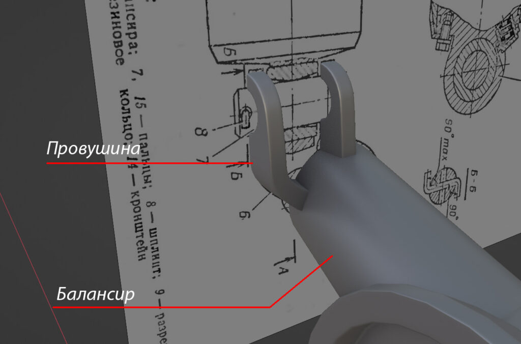
What remains is determining the correct position of the mounting eye on the balancer. But I can fit that later using the general BMP blueprint when installing the running gear on the hull. That’s also when I will adjust the angles.
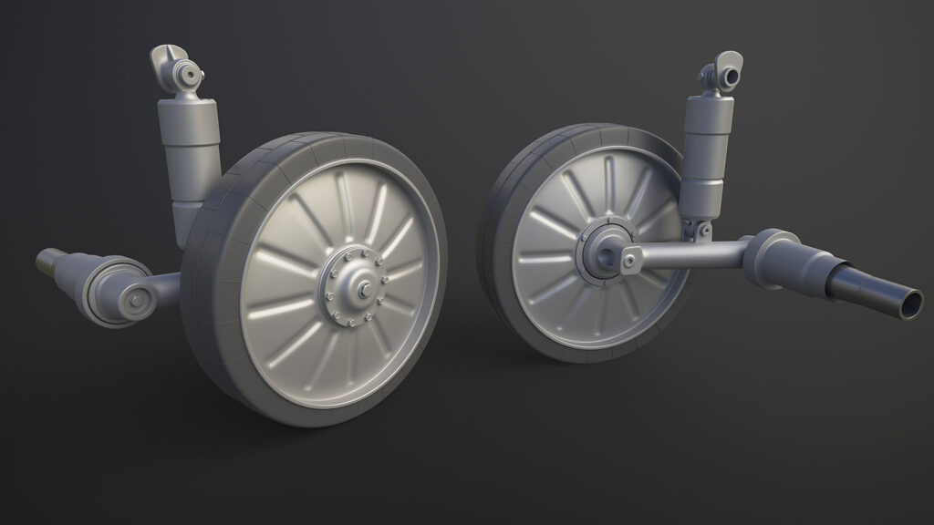
In machinery, many parts are interconnected. If you model one part incorrectly, it can create a cascade of problems. But the rule works both ways—if you have accurate information about one part, you can correctly derive the parts that are connected to it.
Blueprints, manuals, and other references: military-references.com
3D Models Store