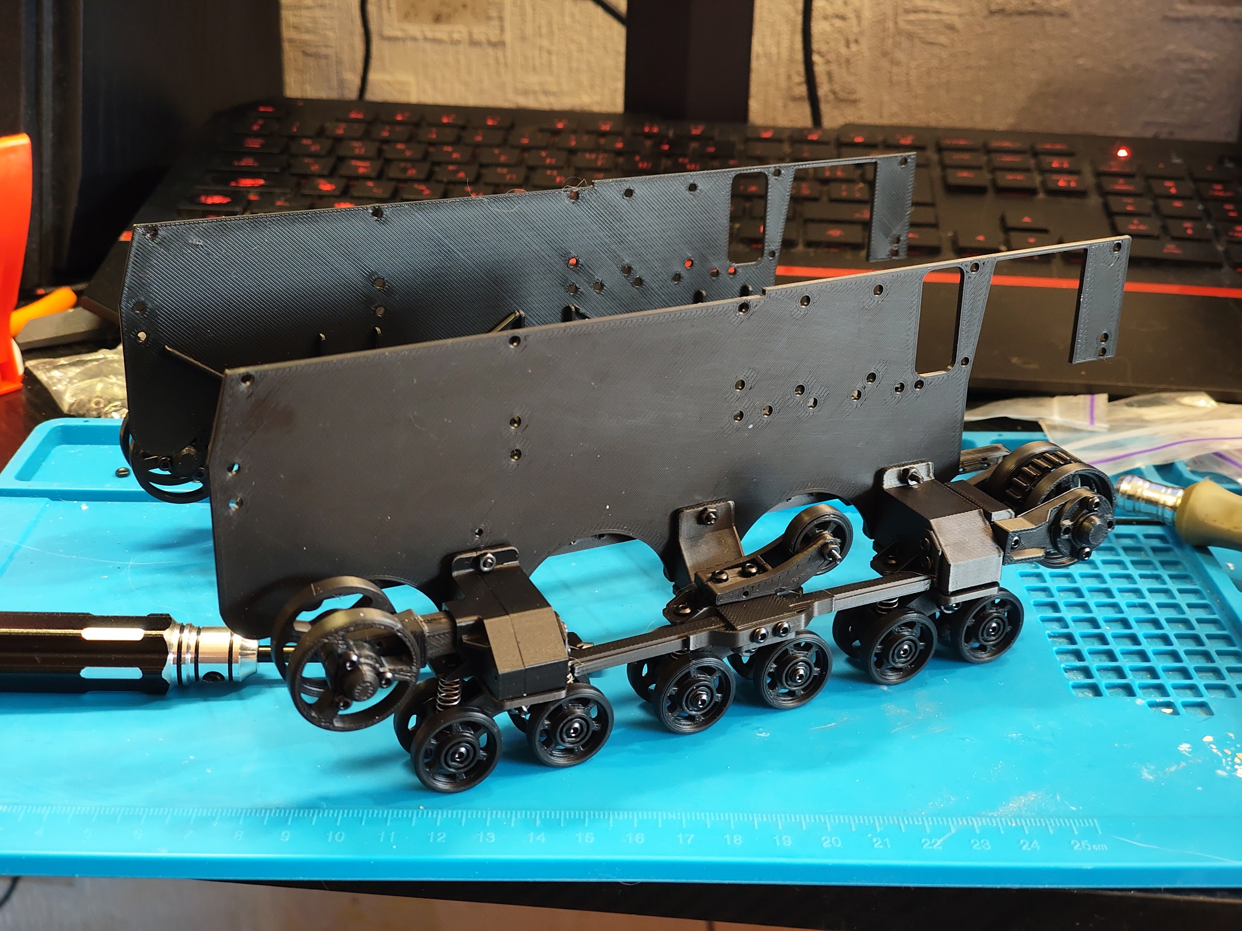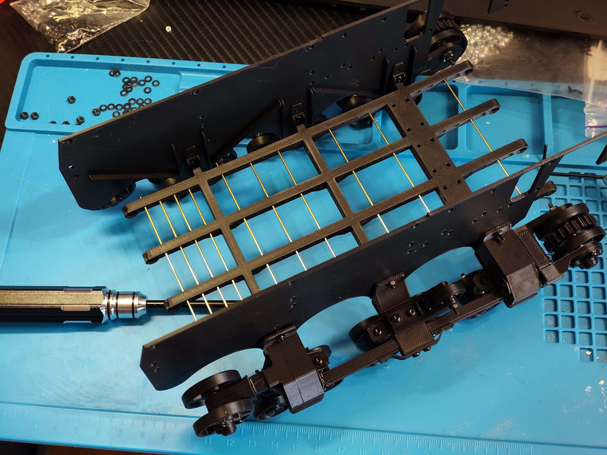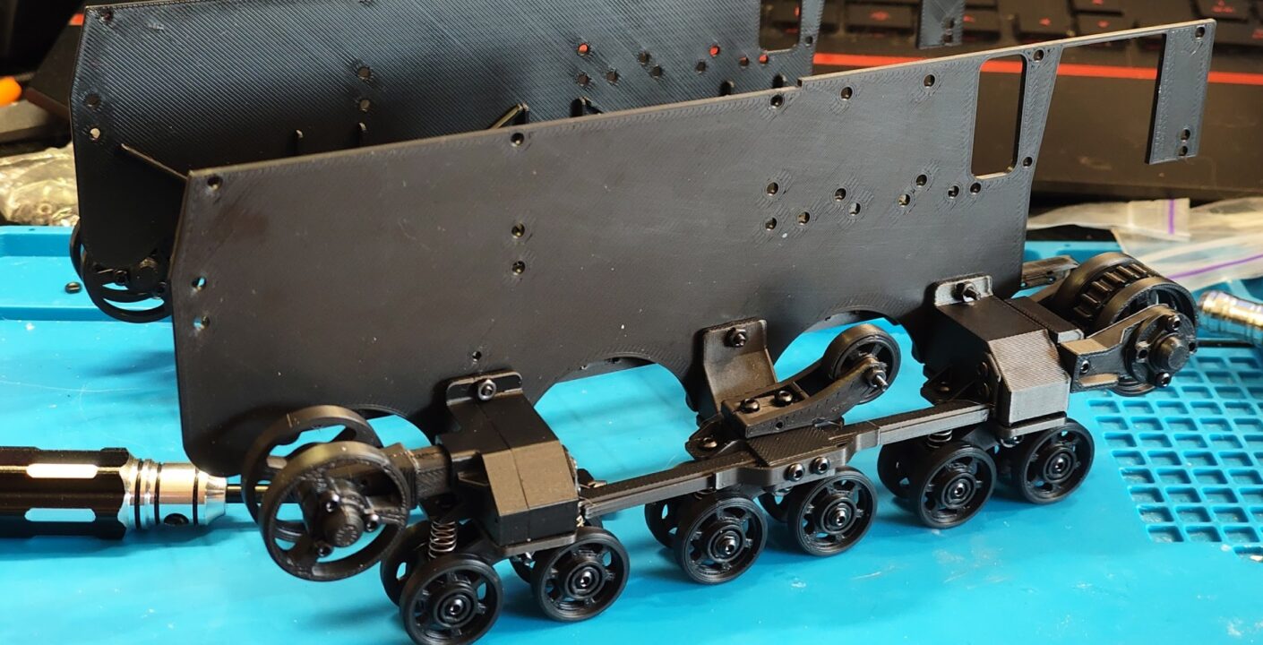
Once the high-poly model is ready, it needs to be prepped for 3D printing. I’m starting with the most important part: the running gear (chassis).
I decided to make a rather large model, specifically in 1/8 scale. I’m doing this so it’s comfortable to work with the mechanics, and so the primary screw size is M2. Working with smaller screws is just inconvenient for me. Plus, I managed to find M2 flanged hex head bolts for sale, but more on that later.
Once the dimensions were set, the first step is removing all the fine details and almost all the fillets on the model. Tiny micro-fillets especially aren’t needed, since FDM printing will never be able to resolve them anyway, but they add a lot of headaches during 3D modeling. If you came to 3D printing from gamedev, the main thing to remember is that a printed part will inherently have soft edges in the real world 🙂
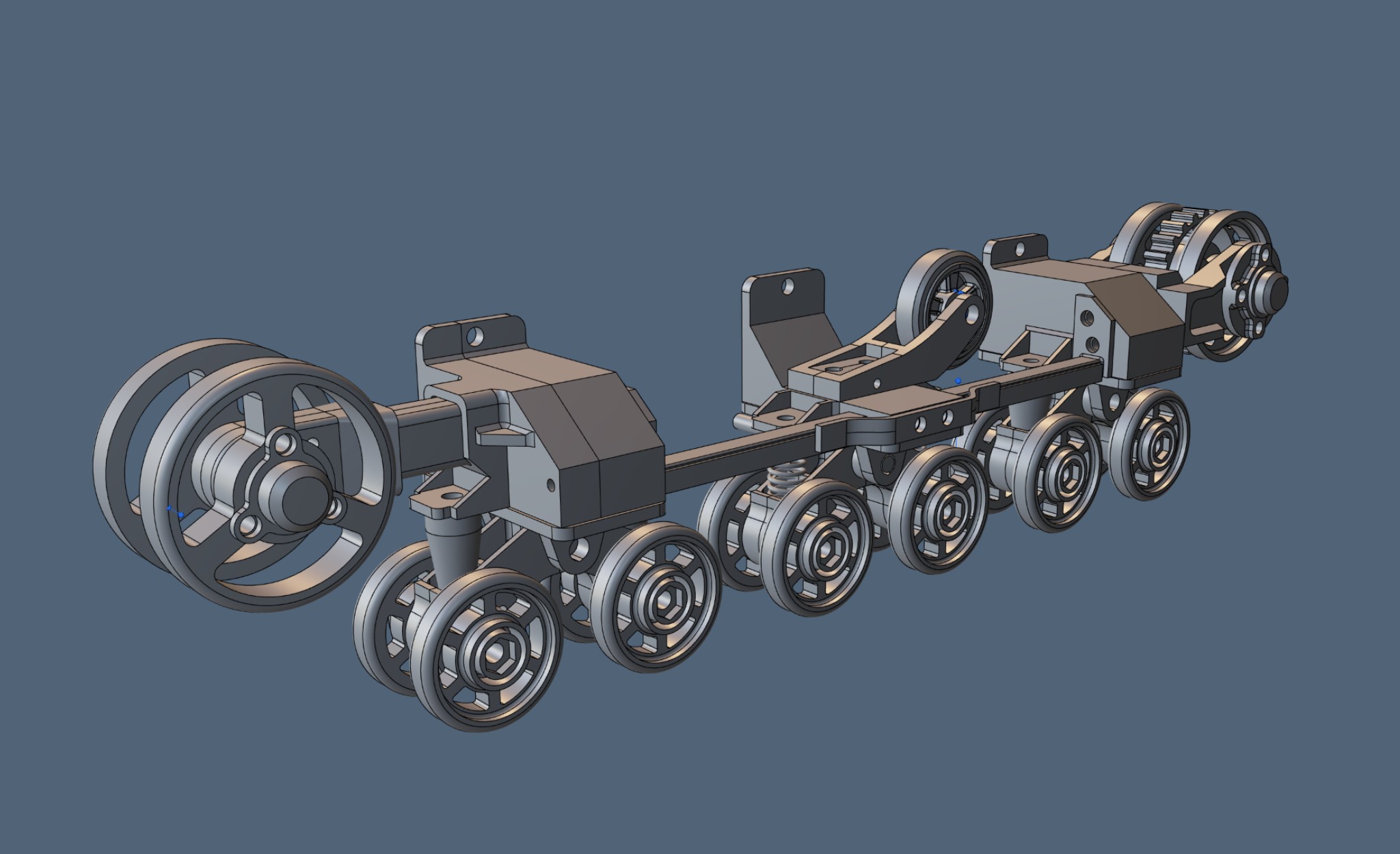
The next step is redesigning the parts to adapt them for FDM 3D printing. I quickly moved past the stage of custom supports and tilting models at 45 degrees, opting instead to print them flat on the build plate. This provides better detailing and faster print times, but makes the model more vulnerable to breaking along layer lines. Therefore, structural components should ideally be printed for maximum strength. However, my model isn’t RC and won’t experience heavy loads, so I’m ignoring that rule in favor of speed and better visual quality.
For this printing method, it’s best to make one side of certain parts completely flat. Usually, this is the side hidden from the viewer’s eye—like on the return roller. I slightly modified the inner side of the road wheels as well.
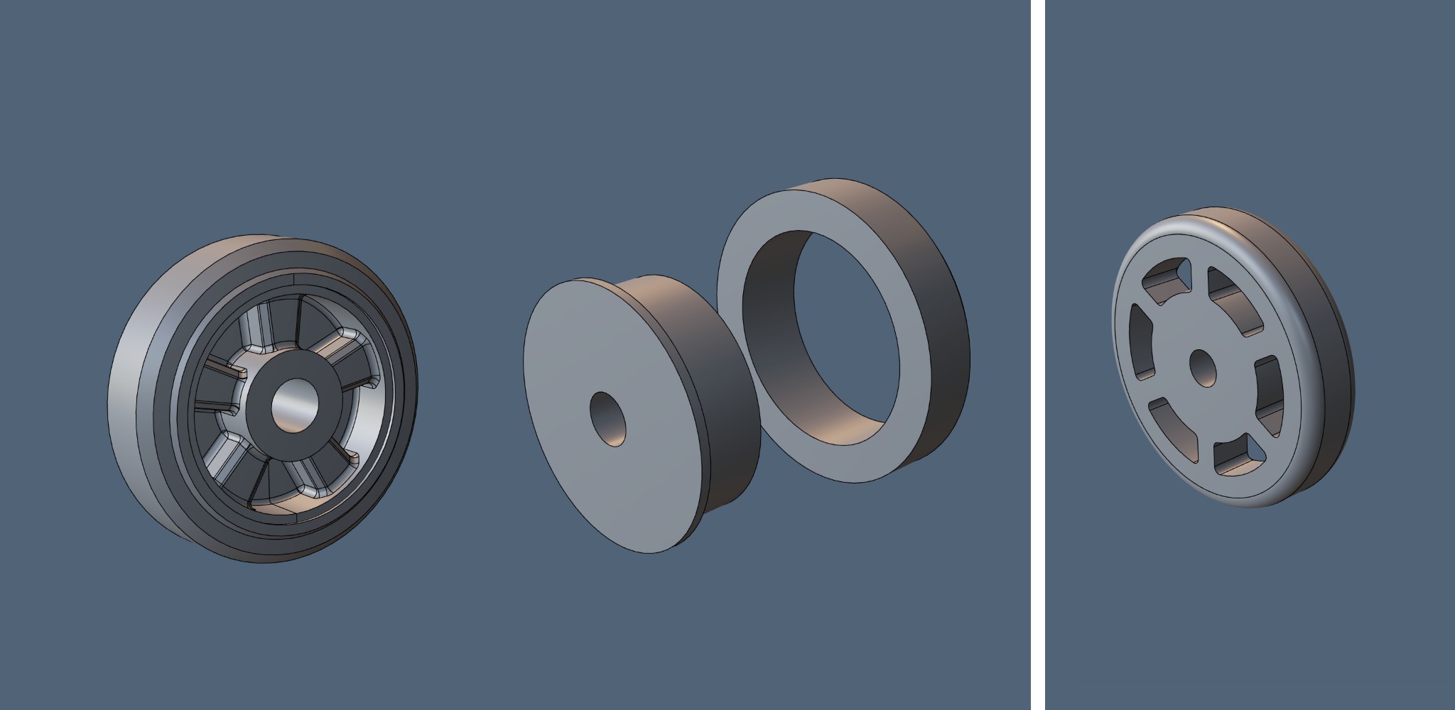
I use a Smooth plate (no downsides found so far), so I can easily “show off” the surface that was touching the bed during printing. Plus, it usually looks better than the top layers.
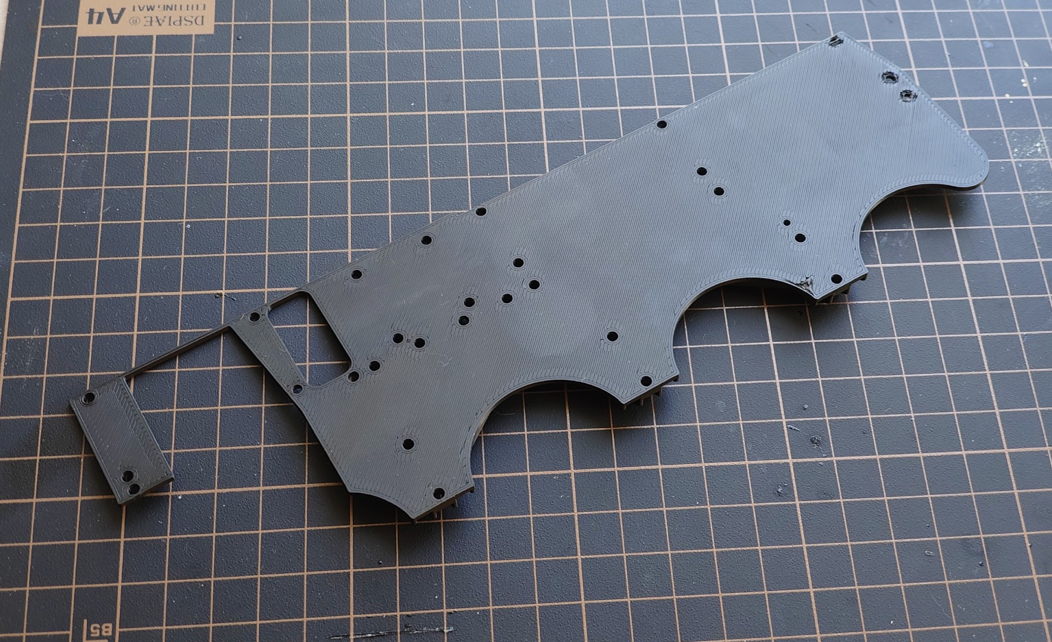
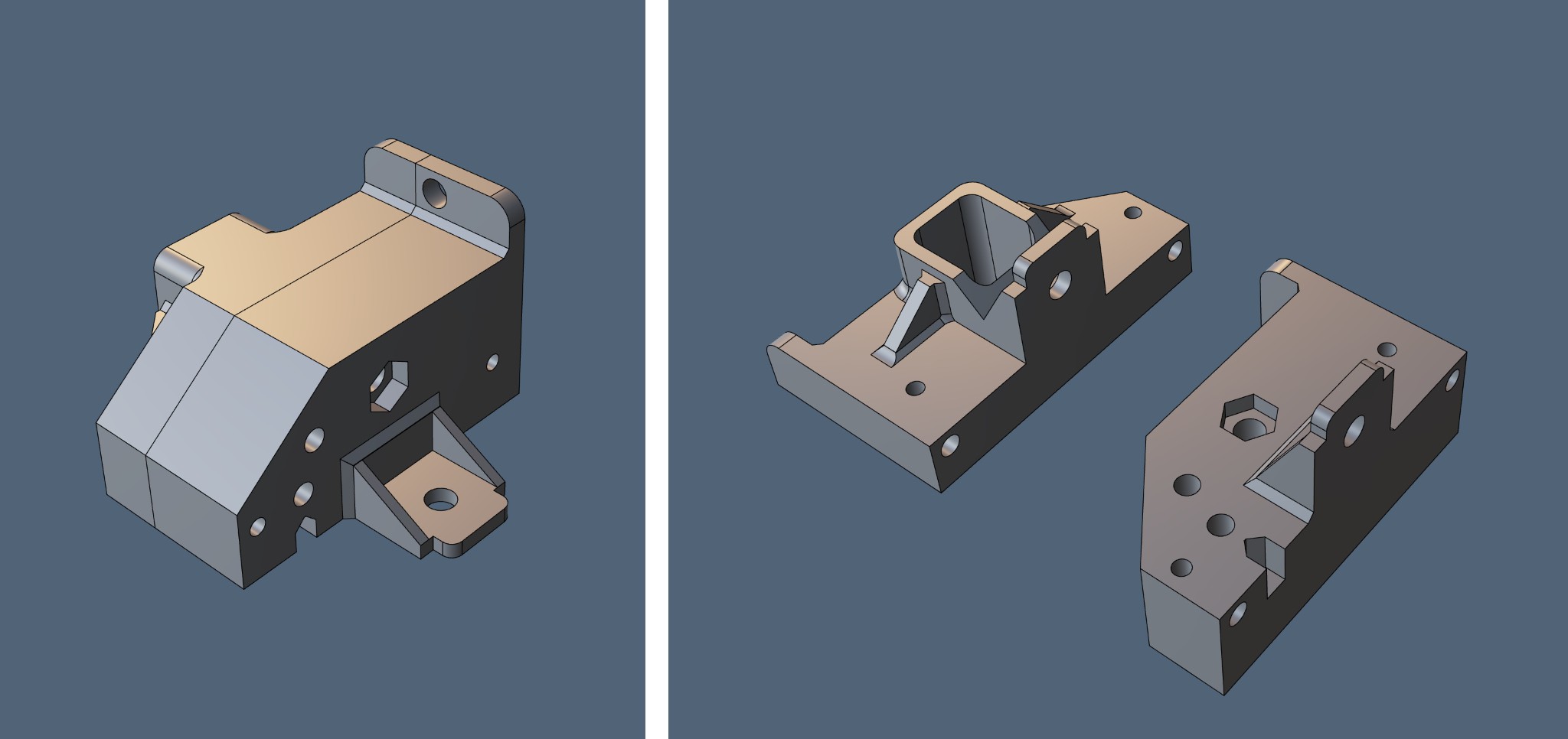
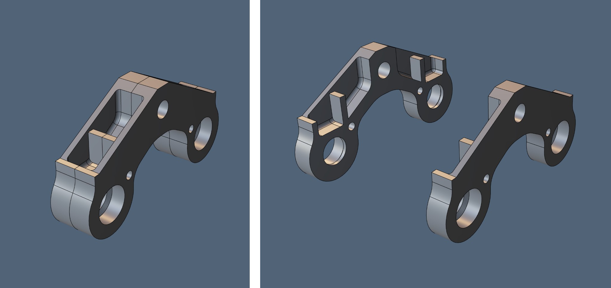
Almost all parts have overhangs if you lay them flat on the bed. Therefore, I slice them all into two halves. To make them easy to glue together, I add two holes for 1mm alignment pins. I apply glue, string the parts onto the pins one by one, and press them together. This ensures precise positioning. Still, you have to watch closely, because micro-shifts can happen since the pins fit quite loosely in the holes and have some play. I do it this way because I find it really inconvenient to forcefully push glue-covered parts onto tight-fitting pins.
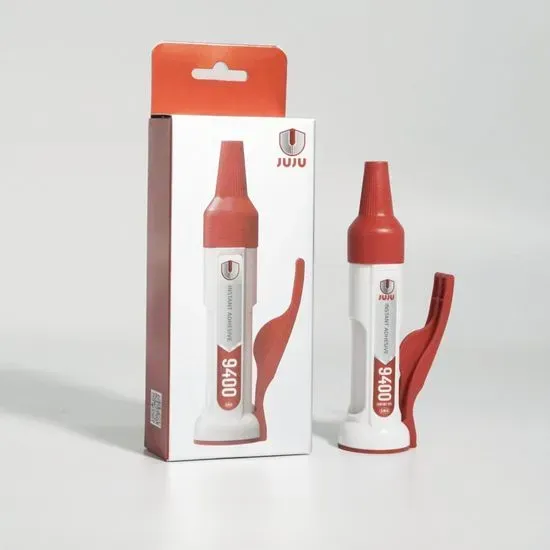
For the glue, I use a medium-viscosity CA. Specifically, JUJU 9400 – it holds incredibly well 🙂
Once I figured out what and how to print, it was time for some entry-level engineering 😀 All the wheels, except for the return roller, run on bearings, so I had to once again figure out how this is all supposed to work. It’s actually simple (with nuances); the main thing is to understand the general principle. With a wheel, there are two options: a moving axle to which the wheels are rigidly attached, or a fixed axle on which the wheel rotates. For the wheel or axle to rotate without wobbling, there must be two bearings.
Since all the wheels on the drone are very thin, I can’t fit two bearings inside each of them. Plus, it would be expensive overall. I mount the road wheels onto an axle that passes through the suspension arm (swing arm). And the bearings are press-fitted into this suspension arm. This way, the axle with the wheels attached to it is the part that rotates.
I ran into some issues with this. The setup should look like this: axle (screw), spacer, bearing, spacer, bearing, spacer, nut. I should add that shoving a threaded screw into a bearing isn’t the best idea, but since this is just a static display model and I don’t have the proper materials on hand (and don’t even know what they would be yet), it’s acceptable. The spacers and the nut clamp down on the inner ring of the bearings and rotate along with it.
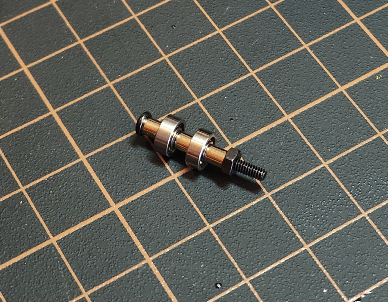
Initially, I thought about 3D printing the spacer. Sure – it’s a tiny tube with a 0.5mm wall thickness and a 2.5mm diameter. You can imagine how “wonderfully” that prints. But the main problem with such printed spacers is that they compress under the force of the nut, which can cause the axle to jam. So, I decided to make everything out of metal. Not from scratch, of course.
Finding bushings or tubes of this diameter in hardware stores is basically impossible. That is, until I stumbled upon a jewelry-making store. They have spacer beads of various lengths and diameters.
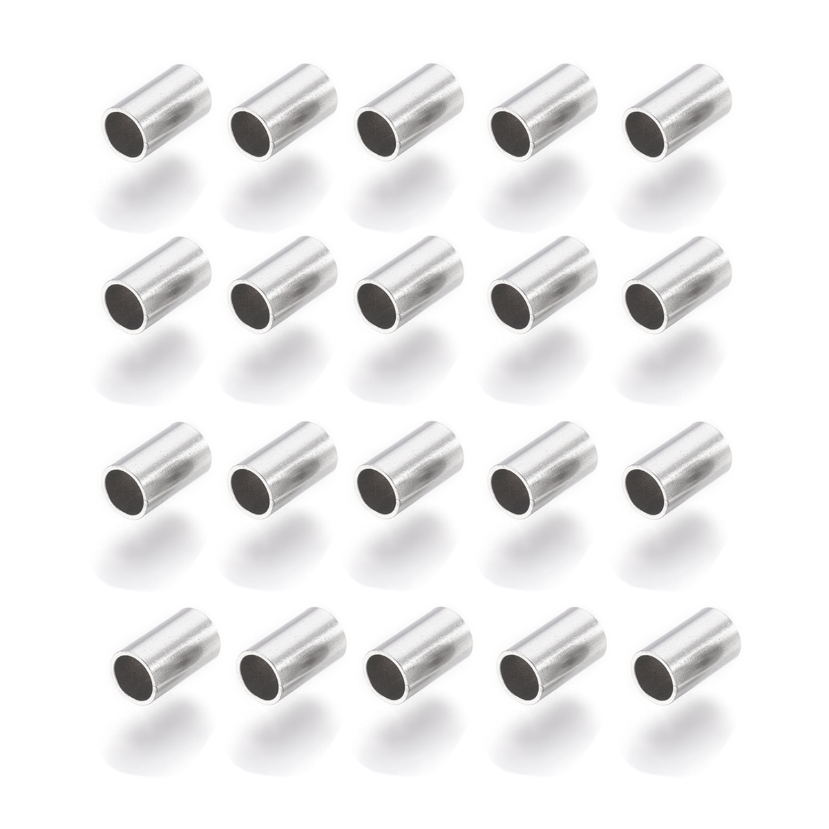
But the shortest spacer I found was 5mm long. Later, I ordered crimp beads. If you find good-quality crimps, they are basically the same little tubes, just shorter, though some might have defects. That 5mm length simply wouldn’t fit inside the suspension arm, so I completely abandoned the internal spacer. And when I got the 6mm diameter bearings, I dropped the spacers on the road wheels entirely; to clamp the bearing, I just used M2 washers with a 5mm outer diameter. I did use the jewelry beads, but different ones and purely as a decorative element. So, all in all, a jewelry supply store is a great source for useful little metal bits.
Without a central spacer, the setup isn’t very reliable. I can’t tighten the nut too much because the inner rings of the bearings start pressing toward each other, immediately causing the bearings to bind. So, I just don’t tighten the nut too firmly.
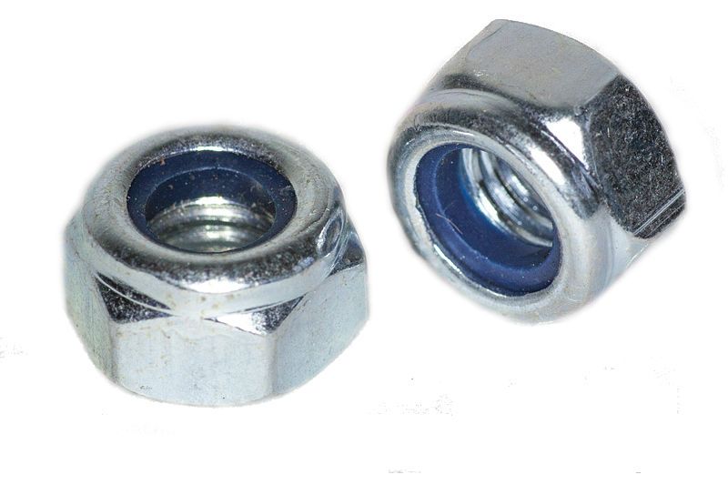
Regarding the nut: moving parts should only use a locknut (nyloc nut) so it doesn’t unscrew on its own. You could also use a special blue threadlocker or an additional jam nut. To me, a locknut is the most convenient option and it looks decent visually.
There’s another nuance with the nuts and the wheel. The hole for the axle has to be larger than the axle itself, which means the wheel wobbles on such an axle. That’s fine if it’s a single wheel—tightening the nut will square it up. But when there are two wheels on opposite ends of an axle, they can tilt slightly while you’re tightening the nut. During rotation, this will look terrible.
I’m actually not entirely sure about the scenario described above anymore, but I did face this issue when I put the wheels on two half-axles, which in turn sat loosely on a screw. That happened when I was trying to fit those 5mm long spacers. Back then, when tightening them, both wheels tilted slightly on their half-axles, and when spinning, they wobbled in a “figure-eight.” Terrible.
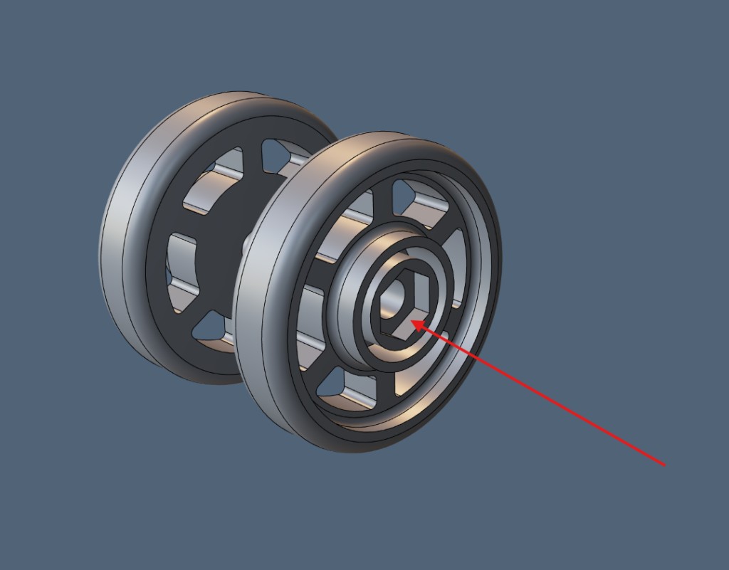
If you need to center two objects under conditions like this, an AI advised me to press-fit nuts into both wheels. When I thread and clamp this whole assembly down, the wheels on both sides straighten themselves out. By the way, it’s also super convenient—the wheels themselves act as wrenches; I just screw them on by hand and can fine-tune each wheel. Of course, there should be a locknut at the very end of the screw. Near the screw head, a standard nut is fine, because it’s clamped from both sides and physically cannot unscrew or fall out.
Overall, you can’t just mount a wheel on a smooth round axle—under load, it will just slip and spin freely on the axle. The only exception is if the axle is forcefully press-fitted into the wheel. Therefore, using a nut is a solid solution for a DIY home setup.
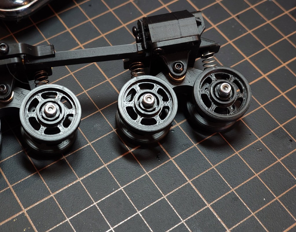
My suspension is built on simple 5mm diameter springs. At the bottom, there is a cup for the spring, and at the top, a nut that prevents the spring from shifting sideways. On the real Termit, there are only two springs per side; the rest are some kind of special rubber shock absorbers. I tried replicating them by printing with TPU 95A filament, but they turned out way too stiff. So, I decided to build the whole thing using springs.
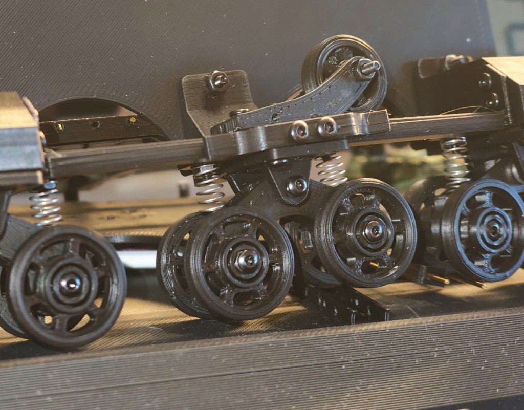
The idler wheel is built the exact same way. Interestingly, I designed a track tensioning system so there won’t be any issues when it’s time to install the tracks. The system is implemented quite simply: the idler is mounted on an arm, and the arm slides into a slot in a bracket. A screw is threaded in from the opposite side, which simply pushes the arm with the idler forward. If you need to move the idler the other way, the track itself takes care of that, pushing the idler back toward the bracket.
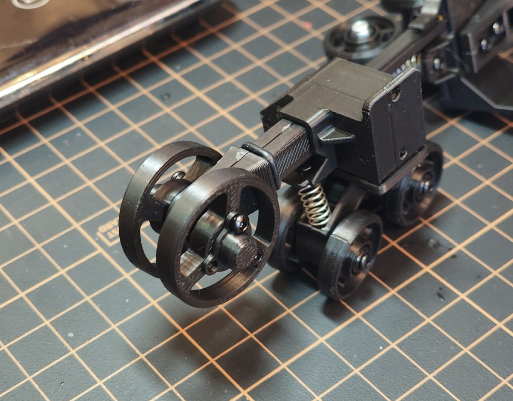
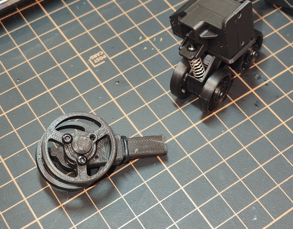
The drive sprocket is purely decorative, as I’m not planning to add any motors or manual drive. But regardless, it has a moving axle here too. I had to remove an additional bracket that exists on the real vehicle, which supports the sprocket wheel. On my model, this bracket simply didn’t fit physically, or it would have had to be half a millimeter thick.
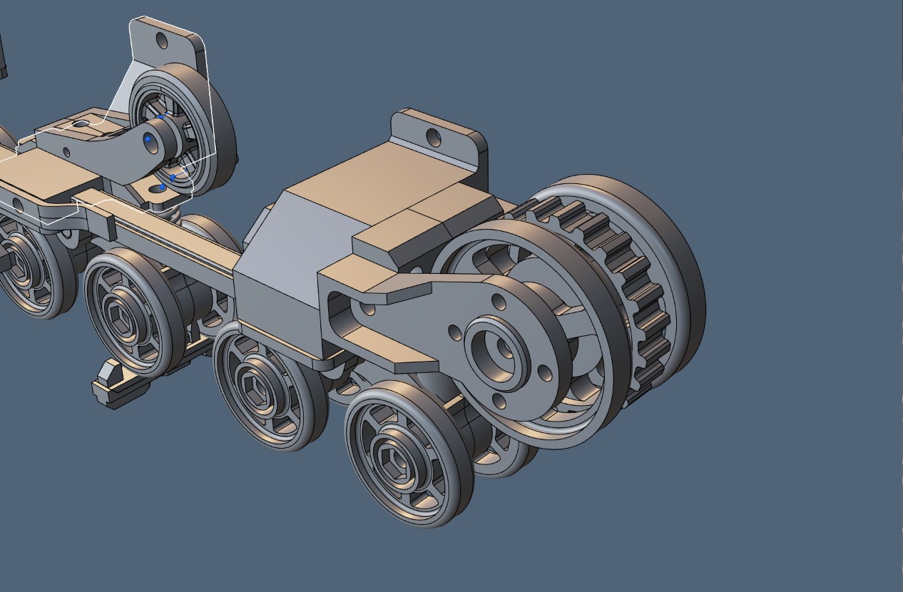
Between the three wheel blocks, I’ve hidden a 2mm metal rod. It’s needed to provide structural strength against the pressure of the tracks, which will constantly try to compress the whole assembly.
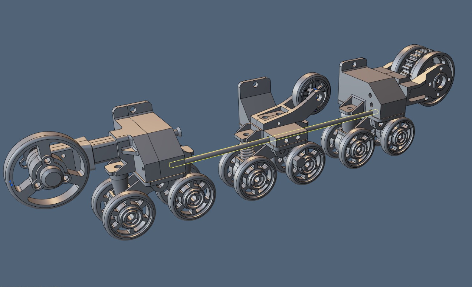
To assemble all of this together, I’ve already designed the frame at this stage and started designing the hull. After engineering the running gear, the “boxes” of the hull seem like a walk in the park, but we’ll see how it actually goes 🙂