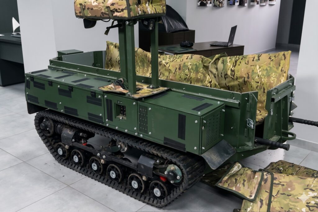
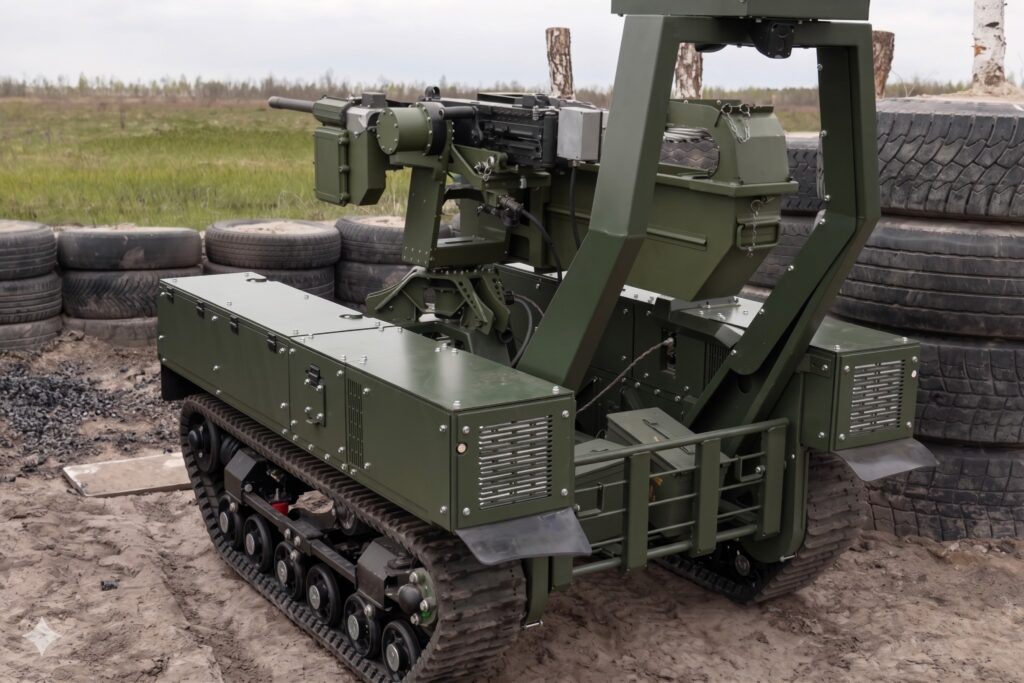
I’m starting work on a new, major (at least for me personally) project. It’s the Termit 2.0 unmanned ground vehicle (UGV). The main challenge of this project won’t be the 3D modeling itself, but rather the attempt to create a 3D-printable model with fully functional, moving parts. But let’s take it one step at a time…
The first, and highly important, stage is creating the base mesh. Naturally, there are no blueprints available. There is only a limited number of photographs of this specific drone version. Therefore, the modeling has to be done exclusively from photos using camera matching techniques. The core idea is to align (calibrate) cameras based on existing photos and start modeling directly from the camera views, i.e., in perspective projection.
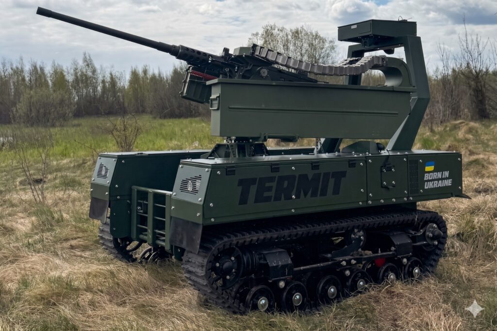
To do this, I gathered photos from various angles. I enhanced the quality of some images using Gemini. This is quite helpful because working with blurry, low-resolution photos is incredibly inconvenient and inefficient. I’m publishing all these photos here. Unfortunately, I didn’t save the sources for all of them, sorry about that. However, most were taken from Tencore’s official pages, and many good, detailed images can also be spotted in an interview on Militarnyi.
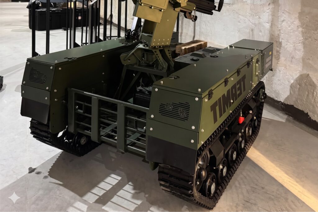
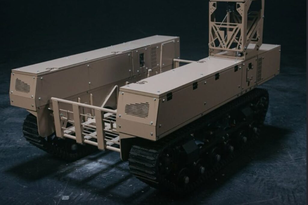
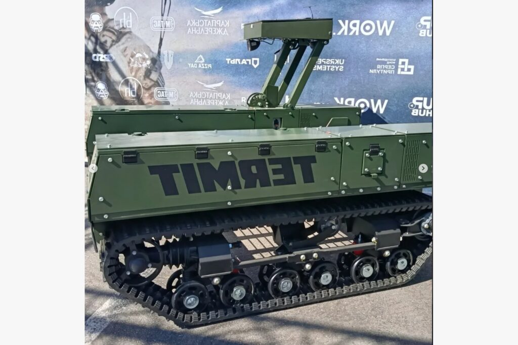
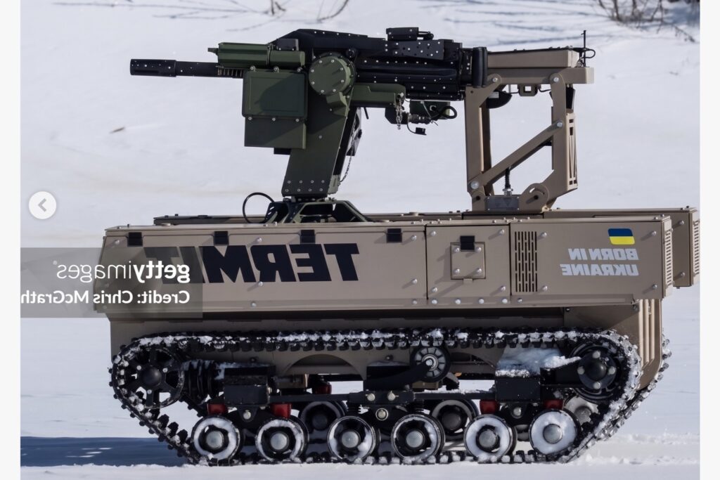
I cropped all the images to have the same aspect ratio. You might also notice that some photos are mirrored. The drone is mostly symmetrical, so I mirrored a few photos to work on just one half. I’ll mirror the other half of the model later.
For setting up cameras from photos, there is (if you pull it through a portal from the past) an ancient piece of software called Image Modeler 2009. The program is dead now, but there is still no real modern equivalent. Its main feature is the ability to place and calibrate cameras from photos when you don’t yet have any 3D geometry. On the downside, the software is terribly buggy and unstable. I gave it 2-3 tries and suffered defeat—the program simply threw a calibration error, and all the locators turned red. So, I closed it and moved on to other tools.
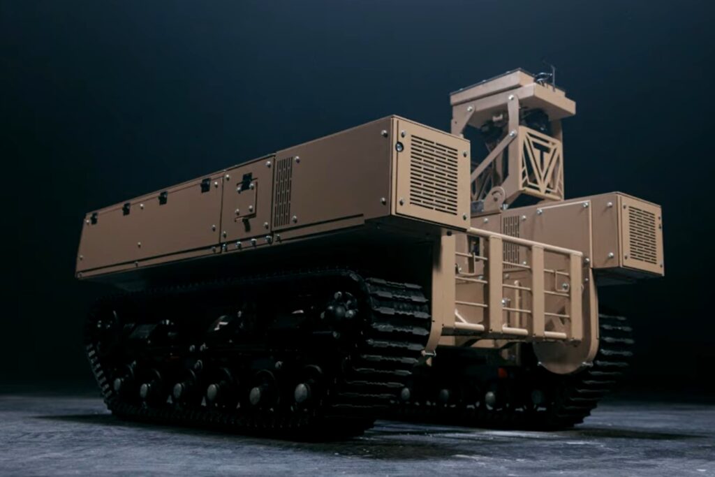
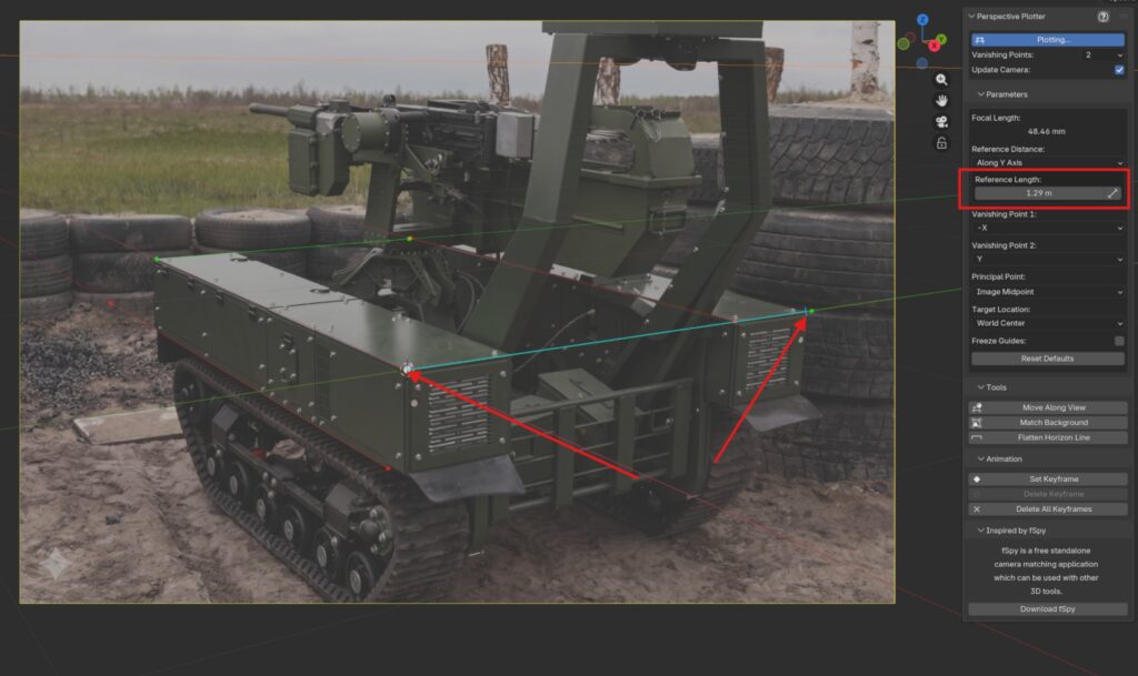
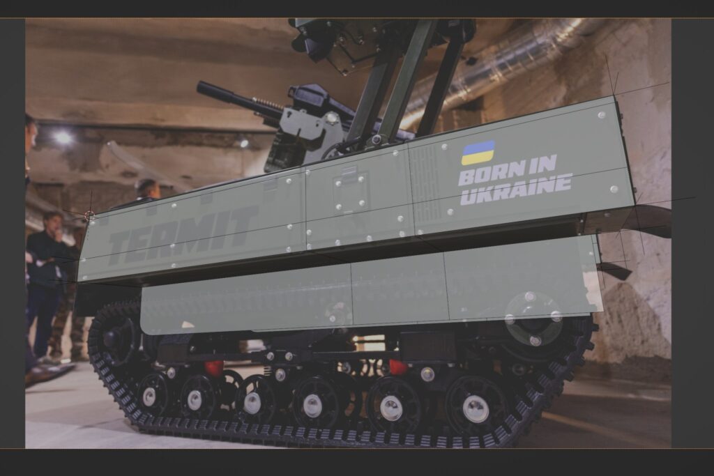
The Termit is essentially shaped like a box. And this is great for working with the Perspective Plotter add-on for Blender, which is similar to fSpy. You can use this tool when the photos feature straight, parallel horizontal (and optionally, vertical) lines. The Termit UGV is composed exactly of such lines and planes. So, in the add-on, I can easily mark these lines along the X and Y axes. I didn’t end up using vertical lines for the Z-axis.
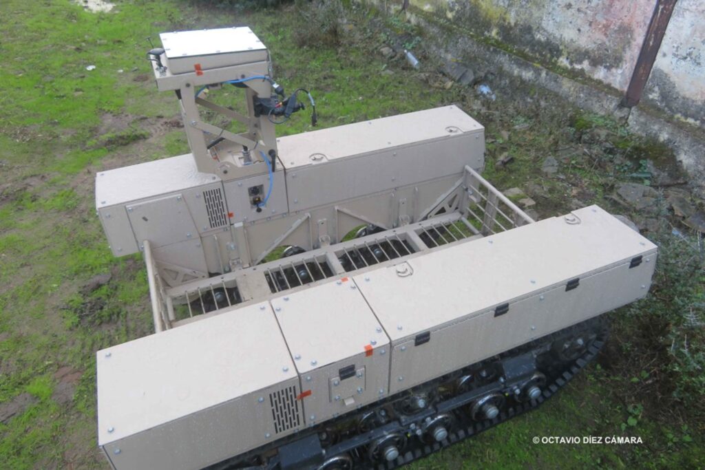
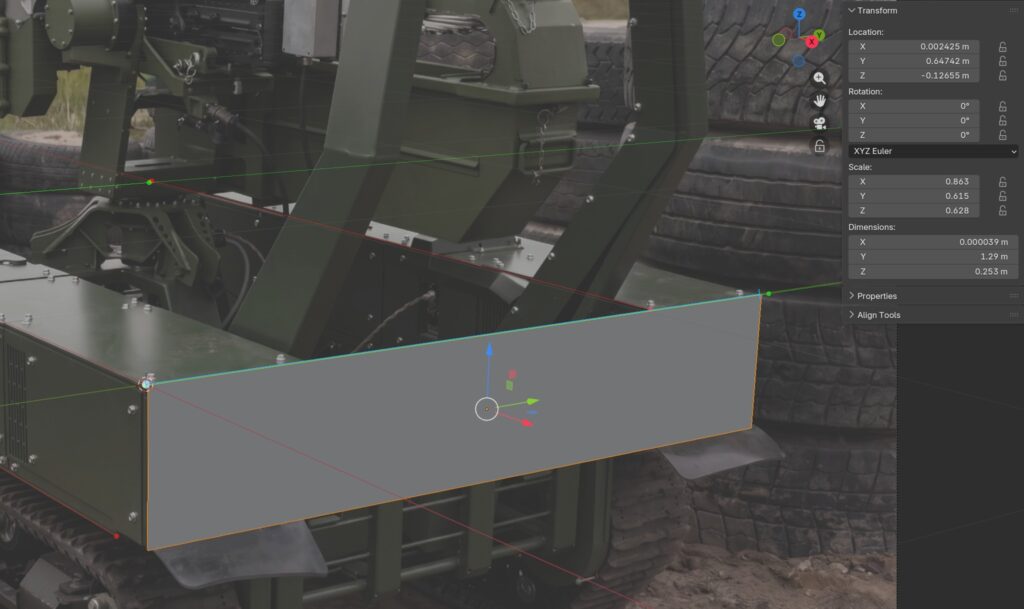
Another really cool feature of the add-on is the reference dimension. After all, once you’ve determined the perspective distortion using lines (basically calculating the focal length of the lens that took the photo), the “Distance to Object” parameter remains unknown. Perspective Plotter offers two options: either set the distance manually, or input a reference length. In my case, this value is the drone’s overall dimensions, which I found on the manufacturer’s website. I set the drone’s width (1.29m) as the reference length, specify which axis this value applies to, and stretch a blue line segment from one edge of the drone to the other. This blue segment now represents exactly 1.29m.
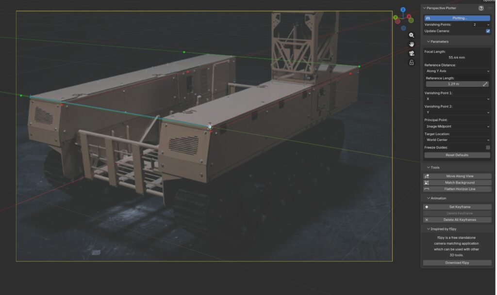
This means I can now create a plane with a width of 1.29m and position it appropriately so that its proportions match the photo. This will be the starting point for building my model. However, there is a nuance: we need to determine the exact position of this plane. At this point, I’m still figuring out the “correct” way to do this, so I do it quickly my own way 🙂 I just move the plane around until it aligns with the photograph. The key here is adjusting its position without messing up the dimensions.
The problem is that when I set up the other cameras, their photos won’t match this plane. There are two ways around this: either try to tweak the camera’s position and distance using the add-on’s parameters (you can’t move the camera manually because all changes reset when you switch back to Perspective Plotter), or do what I did—a “crutch” method. This involves simply duplicating the existing geometry using Alt+D (creating an instance) and moving the duplicate so it aligns with the new camera’s angle. I only change the location, not the geometry or scale. This way, I have a dedicated piece of geometry for each camera view.

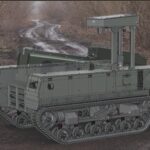
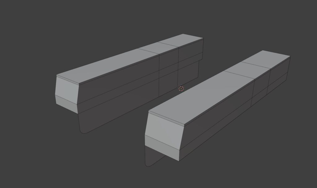
This approach is perfectly justified for me because Perspective Plotter is just an intermediate step. I use this add-on to block out a very basic geometry that captures the drone’s key design points: overall dimensions, large shapes, and major components. In my case, this means the general outlines of the hull boxes.
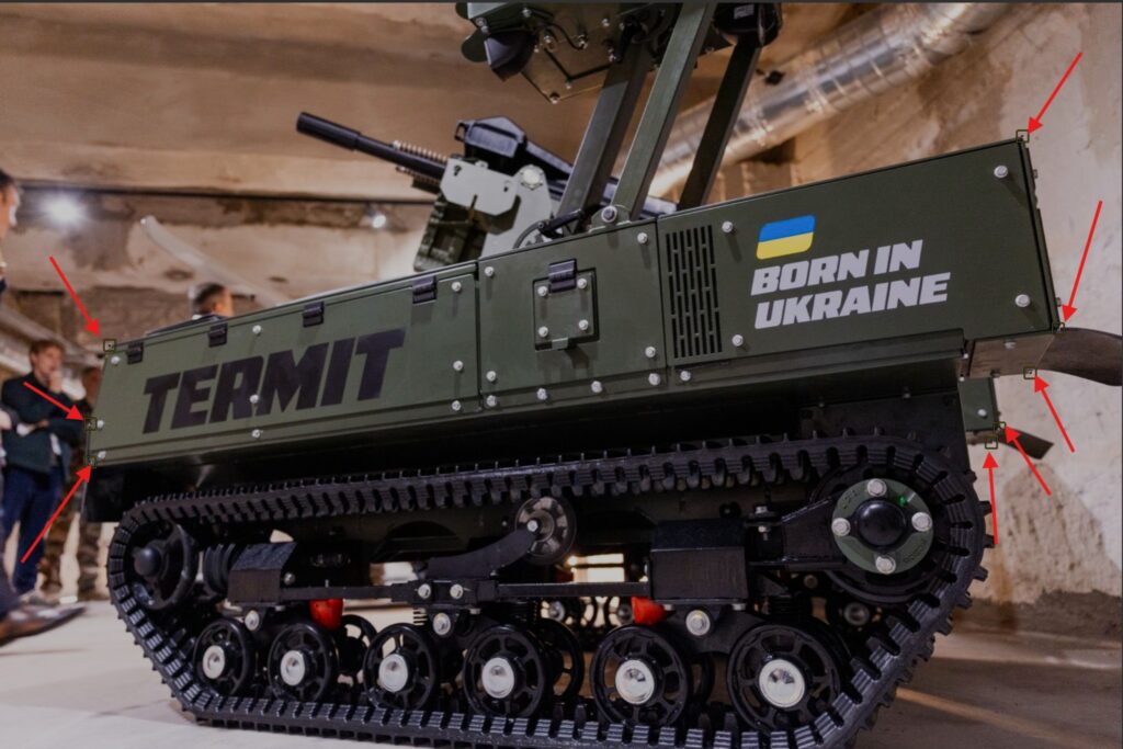
At this point, the work with Perspective Plotter is done. I center the geometry and export it as an FBX, because next I need to switch over to Blender 4.0 to use the legacy Camera PnPoint add-on. There’s a tutorial for it on ArtStation. Inside it, I do the final camera calibrations using the same photos from Plotter, and I can easily add new photos as well. The core function of this add-on is that it calibrates cameras based on existing geometry. I place markers on the 3D model, and then place corresponding markers on the photograph. The add-on generates a camera and positions it so the geometry matches the photo perfectly. Because of this, there’s no need for extra manual tweaking of cameras, distances, reference lengths, or geometry placement—the add-on handles it all automatically.
It’s worth noting that this technique assumes the 3D object is an exact replica of the object in the photo. As we know, perfection doesn’t exist, so there will always be slight camera calibration errors or minor inaccuracies in the model itself. The important thing here is to ensure there are no critical errors. If there are MASSIVE discrepancies between the model and the photo, you should check if your locators are placed correctly, or if the model itself has severe dimensional flaws. For example, if the model’s overall width is significantly off, the add-on won’t be able to “stretch” the model over the photo during calibration, resulting in glaring mismatches, specifically in width. But if you did everything right in Plotter, you shouldn’t face these issues. Minor calibration quirks will still happen, and that’s perfectly fine with me.
Locators/markers should only be placed on spots that are clearly visible in the photo. The add-on is a bit glitchy, so I create a separate scene/file for every single camera/photo. Honestly, I’m just used to doing it this way. Once all the cameras are configured, I open my main Blender 5.0 file and Append these cameras into a single scene. Usually, the background images for the cameras link up automatically. I also import that base mesh I used for setting up the cameras.
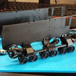
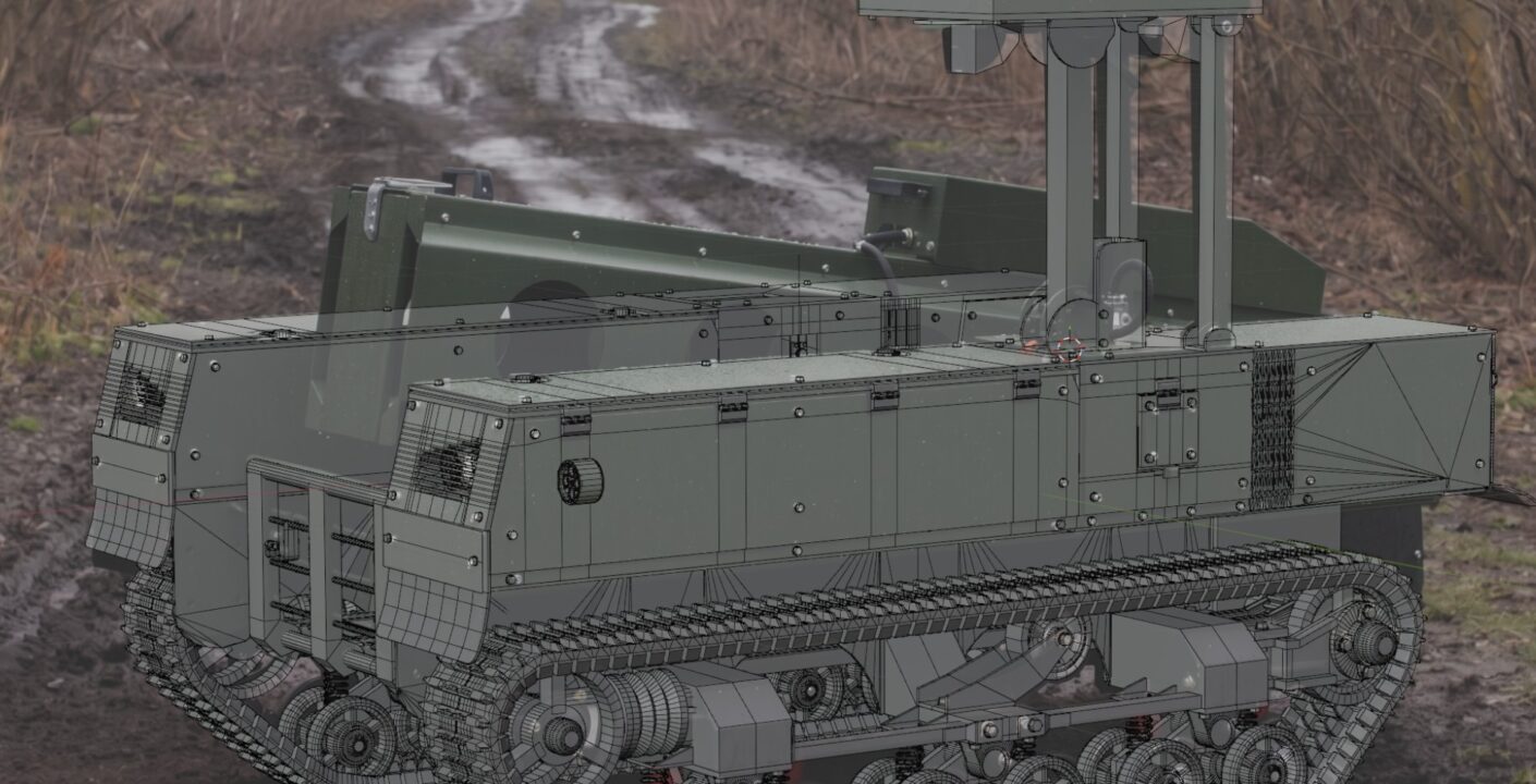
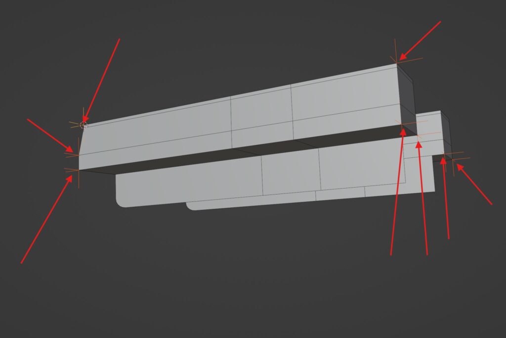
Now, this is the final scene where I actually start building the base mesh. I switch between the various camera views and work on a single piece of geometry, with no duplicates. The tricky part of this modeling method is that it can sometimes be hard to determine the exact position or size of an object. For instance, figuring out the wheels’ mechanics-especially accurately defining and placing the idler wheel (linivets) in the suspension—is always a headache. You have to find a compromise between the position and diameter of the wheels, since I don’t have precise data for either. The only thing that saved me here was the track, as I had one photo taken directly from behind. This allowed me to determine the exact width and placement of the tracks. From there, I modeled the rest of the wheels relative to the tracks.
Next, I will be moving to CAD software (Plasticity), like Plasticity, to create the clean, highly-detailed model. As much as one might want to avoid it, it’s a necessary step to properly prepare the model for 3D printing. A solid CAD model is essential because engineering moving parts with a polygonal mesh is extremely inconvenient.
I’m not a professional instructor, so I realize I might not have explained some parts perfectly clearly. If you have any questions, feel free to join my Discord server to discuss this or any other topics!